| Chris Sutton's Speedster Project |
Chriskate : Home : Separation : Shortening : Front Beam : Pan Powdercoating : Brakes : Transmission : Engine : Photos : Electric Photos |
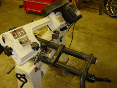 One tool
that I bought a while back when building Gocarts with a friend, was a
horizontal band saw, for cutting metal. If you do much metal fabrication this
tool is a must. For the longest time we were cutting things with a vice and
sawzall and were never able to get any sort of angled cuts correct, like when
you need two 45's. We ended up doing some creative welding to fill in gaps,
which doesn't make for the strongest weld.
One tool
that I bought a while back when building Gocarts with a friend, was a
horizontal band saw, for cutting metal. If you do much metal fabrication this
tool is a must. For the longest time we were cutting things with a vice and
sawzall and were never able to get any sort of angled cuts correct, like when
you need two 45's. We ended up doing some creative welding to fill in gaps,
which doesn't make for the strongest weld.
So, if you have a horizontal band saw, then adding the adjuster to your front beam is for you! The first step is to get the hardware. In my case I bought some Front End Adjusters from CB Performance. There really were no instructions that came along with them, so for sure, you will need to learn from my experiences.
Step 1 is to take apart your existing front beam. This is a really messy thing as there is a lot of grease inside the beam tubes where the "springs" live. If you haven't already done this, take apart all the stearing linkages, front spindle, and stearing box.
While we are taking about front spindles, I opted to get a dropped spindle as well as doing the adjustable front beam. I bought 2 1/2" Dropped Spindles from CB Performance. Some people say all you need to do is the adjustable front beam, other say just the drop spindles, the build manual says all you need to do is just "lower" your front beam, which is sort of like adding in the adjuster, but welding it back in place fixed. I think doing the drop spindle and the adjustable beam is the way to go because it gives you the greatest flexibility.
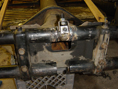 (Preparing to weld adjuster. Beam must be bolted to pan before welding.)
So, once you have all your parts and have taken the basics off the front beam,
you should be left with the 4 "arms". These are attached to a pack of tortion
springs in each of the beam tubes. There should be a big allen screw in the
middle of each beam, loosen this (or take it out completely). Then loosen the
big allen screws on one arm. It should pull off and you will see this big
greasy mess inside the tube. If you poke around, inside all this grease will be
a pack of 4 long metal slab "springs". Two are skinney and two are a bit
thicker. Now, go to the arm on the other side and you should be able to pull
the springs out through the beam by the other arm. A good reference for all of
this is the blue Bentley VW Repair manual, because again, I'm not the expert and
I'm typing all of this up about 9 months after doing it, sitting here in my
kitchen, drinking a beer. So refer to the manual again. It should tell you all
you need to know about taking it apart and making sure there really is something
to reuse.
(Preparing to weld adjuster. Beam must be bolted to pan before welding.)
So, once you have all your parts and have taken the basics off the front beam,
you should be left with the 4 "arms". These are attached to a pack of tortion
springs in each of the beam tubes. There should be a big allen screw in the
middle of each beam, loosen this (or take it out completely). Then loosen the
big allen screws on one arm. It should pull off and you will see this big
greasy mess inside the tube. If you poke around, inside all this grease will be
a pack of 4 long metal slab "springs". Two are skinney and two are a bit
thicker. Now, go to the arm on the other side and you should be able to pull
the springs out through the beam by the other arm. A good reference for all of
this is the blue Bentley VW Repair manual, because again, I'm not the expert and
I'm typing all of this up about 9 months after doing it, sitting here in my
kitchen, drinking a beer. So refer to the manual again. It should tell you all
you need to know about taking it apart and making sure there really is something
to reuse.
Once you have everthing out of the front beam, you can now start the process of adding in the adjuster. The first thing to do is score a horizontal line across each beam where you took the existing hex screw out. You will eventually be cutting out this part of the tube so you need to know where the screw was so you can get things back together in about the same place so the springs load correctly. Scribe a line that goes about 4-5" from the center in each direction. Then measure how wide the adjuster is, and cut almost exactly that much from the top tube. Now, bolt the beam into the pan and put the adjuster into gaping hole in the tube you just cut out.
Now for the important part, lining it up. It all comes down to looking at the adjuster and trying to figure out where the old hex screw was, and where the new hex screw will go that clamps into the spring packs. The objective here is to lower the front end, but if you are also adding drop spindles, then the objective of the adjustable beam is really to be able to go up or down from the original location.
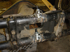 (Adjusters welded in. Make sure they go the right way! These are WRONG!)
The way I put my adjusters in, I didn't leave very much room to adjust up at
all, and in hind sight would have done it more even. Still not having any sort
of body or weight in the front to test out what the final front end would look
like it's sort of a crap shoot at this point and hope for the best.
(Adjusters welded in. Make sure they go the right way! These are WRONG!)
The way I put my adjusters in, I didn't leave very much room to adjust up at
all, and in hind sight would have done it more even. Still not having any sort
of body or weight in the front to test out what the final front end would look
like it's sort of a crap shoot at this point and hope for the best.
Once thing that I totally screwed up on was putting the adjusters in backwards. Now, lets think about how all of this works out and where all the stress is on the system. In the pictures on the left you will note that the adjusting screw and nut is pointed up. Well, if you think about how the front end suspension works, the the way the arms twist the spring pack, the twist on the springs when the arms are going up (say when you hit a big pot hole) is down, away from the adjusting screw and bolt. Which means the only thing which keeps things from moving is the tightness of the other bolt in the adjuster. So, in the pictures here they adjusters are in upside down. Of course the way all this works is that I had both welded in before I thought all this through. So I had to cut them out and weld them back in again. All part of the project and a big learning experience. In the end, if my adjusted beam does not work out, I can always go back and get a beam with an adjuster in it and replace this one if it doesn't work in the end.
Next up, Pan Powdercoating.